Honeywell City Technology Industrial Gas Sensor
Frequently Asked Questions
- What is industrial gas sensors?
Industrial gas sensors are purposefully designed to measure a variety of toxic and combustible gases to help keep workers safe in harsh commercial and factory environments. -
Are the iseries sensors interchangeable? If so, how and why?
All iseries sensors have the same form factor, pin-out, supply voltage and communication protocol, hence they are interchangeable. - All sensors in the range will work with a supply voltage from 3.1 V to 3.3 V (between V+ and V-)
- The sensor has a UART protocol to communicate with the instrument with chip select option
- All intelligent sensors have the same dimensions and communication
protocol, regardless of the type of technology
- What communication protocol do you use and how do you
communicate with the sensor?
UART (universal asynchronous receiver-transmitter) with Chip Select. The communication is achieved by sending data packs through the receiver (Rx), transmitter (Tx) and Chip Select (CS) pads on the back of the sensor. Consult the iseries communication standard (Smart Device Communication Standard) for additional information. -
How do you interface multiple sensors on one UART set of
lines?
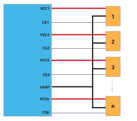
The instrument is coloured in blue and the sensors are represented as orange rectangles. The UART bus (black line) consists of the receiver (Rx) and transmitter (Tx) lines. Chip Select (dark blue line) alternates the communicate between sensors. The red line represents the sensor supply voltage (V+ & V-).
To alternate between different sensors, it is necessary to select the sensor to be used by using the Chip Select pad in the back of that sensor. To wake up the sensor, a falling edge (a high to low jump) needs to be sent to CS; this will activate the communication port. To deactivate the communication port, a rising edge (a low to high jump) needs to be sent to CS. - What is a pre-calibrated sensor?
All iseries sensors are calibrated during manufacturing, when the calibration data is programmed into the sensor. The sensors are fully calibrated when the sensors are installed using the recommended sealing and mounting proceedings (refer to sensor mounting application note). For the calibration to be valid in all instrument types, it is often necessary to compensate for the effects of external replaceable membranes, pumps or sampling systems on the sensor reading. The effects of these are very dependent on the gas type. To account for these effects, a compensation factor (also called User Factor) must be implemented. All iseries sensors are pre-calibrated. A pre-calibrated sensor becomes fully calibrated when a User Factor (UF) measurement has been provided for the instrument, and Honeywell has inputted the User Factor into an allocated User Factor Index (this process is done during manufacturing). The defined UF will help identify what type of instrument it is, and in this manner, the installed sensor will be fully compensated and calibrated. -
How do I account for differences in instrument design?
Can I trust the pre-calibration data to be the same when I plug
it into my instrument?
If the sensor is installed inside an instrument, the air path of the gas is different to access the sensor. Likewise, if an additional membrane is used on top of the sensor or a gas pump it uses, the gas diffusion would be different. In general, if the gas dynamics change, the measured concentration value would also change; to compensate for this, it is necessary to change the User Factor accordingly. We simplify this by providing User Factors (UF) built into the sensor for our recommended gassing designs and can also include customerspecific compensation factors if required. The instrument simply needs to tell the sensor what type of gassing design it uses, via a UF index, and the sensor uses its own internal lookup table to select and apply the appropriate compensation factor.
-
How do I determine the User Factor (UF) for my instrument?
To define a new User Factor, you would need to gas test a pre-calibrated sensor in your instrument for each type of sensor. The ratio between the applied gas concentration and the gas reading will be the User Factor. For instance, if you are applying 50 ppm and your instrument is ‘seeing’ 45 ppm, the user factor will be UF= (45/50)*100=90. To accurately determine your UF, we recommend you use at least five sensors and five instruments. This will allow you to obtain representative data to confirm repeatability. -
Can I implement a new User Factor directly into my sensor?
How many UF indexes are available?
To implement the new UF, you would need to measure the gas concentrations in your instrument (refer to question 6). Once the UF ratio is determined, the new UF index can be implemented by Honeywell in the sensor configuration file. This process can be done only during manufacturing. There are ten allocated User Factor indexes: two User Factors are already implemented (no additional membrane and with recommended membrane), two reserved and the remaining six can be customized. -
Why does the UF have to be selected each time the sensor
is powered up? Why can’t it be stored in the non-volatile
memory?
If the sensor is transferred to a different type of instrument, the selected UF may no longer be valid, causing an incorrect reading. Setting the UF each time ensures that it is already correct. -
How does OEM lock work? How do I get it to work for me?
The OEM lock is a lock code that is set between your instrument and sensor. It allows you to verify that no other sensor (other than yours) can work on your instrument, i.e. the sensor needs to be purchased directly from you. OEM code is set by Honeywell during sensor manufacturing with the code to be provided by the OEM. - Can you change the OEM lock code?
OEM and partner codes can only be set once, after that it is not possible to modify them. -
Why is a unique OEM lock code needed?
If you don’t check the OEM lock, and the user has fitted a sensor from another OEM, it might have a UF defined for a particular UF index but it won’t be the right one for your instrument. -
How do I mechanically connect to the sensor?
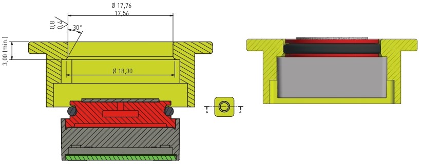
The O-ring around the sensor allows the user to seal the sensor. The recommended dimensions for the bore diameter are from 17,56 mm (min) to 17,76 mm (max), and the surface finish must be longer than 3 mm, as depicted in the following figure. -
How do I electrically connect to the sensor?
There are five pads in the back of the sensor, corresponding to the positive supply voltage (V+), ground (V+), transmitter from sensor to instrument (Tx), receiver from instrument to sensor (Rx) and Chip Select (CS). - What type of electrical connector mechanism can be used to
connect the sensor?
Connection should be made by using a spring contact or spring-loaded pin. -
Can I solder the sensor?
Under no circumstances should intelligent sensor pads be soldered to, as this can cause irreversible damage to the sensor. -
How do I gain IP68 seal on my instrument?
To seal around sensor, please refer to mounting application note. -
What type of information can I get from the sensor?
The instrument (computer, microcontroller, etc) can request the following instructions:
• Acquisition of parameters, concentration readings from sensors
• Calibration of sensors
• Request of calibration parameters and data from sensor
• Set alarms, deadband, real time clock, OEM lock and other sensor parameters
Additionally, it is possible to set the sensors parameters -
How do I interpret the data?
The communication between the instrument to the sensor (and vice versa) is carried out by the transmission of data packs.
The format of the data packets will remain the same for transmitted and received packets; nevertheless, the size of these would vary from command to command. The packets are divided into eight different subsections: SOP, Version, Length, SI, CMD, Data, CRC and EOP; where SOP is the start of packet, Version corresponds to the firmware version, Length describes the size of the packet (from SI to EOP), AI is an auto-increment index that goes from 0 to 65535 (0xFF FF), CMD the command code, Data the data requested by the command code, CRC the error-detecting and correction code used to detect accidental change to raw data and EOP the end of packet. For a complete description of the architecture of the commands (in terms of bytes), consult the iseries Communication Protocol (SDCS: Smart Device Communication Standard). - What do I have to do to start-up the sensor?
To initiate the sensor, it is necessary to follow the procedure described in the following initiation flow-chart. When the sensor is first powered-on, it will take five seconds for the device to initialise peripheries and load configuration files; once the process is finished, it will automatically go to sleep mode. To wake up the sensor, it is necessary to set Write-Protect off and use GoTo_Mode. As described in the diagram, the OEM code must match, so the sensor can be used in the instrument (otherwise the device is rejected and will not be able to be used by the instrument). -
How do I get gas concentration measurements?
To obtain the gas concentration measurement, it is necessary to use the get_data_pack command (CMD: 0x30, GET_DATA_PACK) and the data format command (CMD: 0x31, GET_ DATA_FMT). In order to get a valid gas reading, it is necessary to ensure that: • The sensor is in work mode • No errors are flagged • No alarms are flagged -
How do I get the End of Life and the Predictive Calibration? Do
I need to configure something to perform these tests?
The End of Life (EOL) and Predictive Calibration are some of the intelligent features found in the iseries. The functions can be called with the use of the Predictive Calibration and End of Life commands. To obtain a valid EOL or Predictive Calibration measure, it is necessary to run an internal diagnostic test; this test runs automatically every 24 hours. However, the diagnostic test is only performed when the sensor is in sleep mode, so it is highly recommended to change the sensor to sleep mode whenever it is not in use (otherwise, the End of Life and Predictive Calibration estimations will not be updated/recalculated, leading to nonaccurate results) -
How and when the End-of-Life and Predictive Calibration are
flagged?
The error and faults can be transmitted to the instrument every time it requests a gas reading from the sensor (GET_DATA_PACK command, CMD: 0x30).
• The Predictive Calibration alarm consists of two different parameters, and the alarm will be triggered when either the countdown or the accuracy threshold are reached (whichever is triggered first): - The Predictive Calibration estimation will depend on the requested accuracy of the sensor. This parameter can be configured by the user: the tighter the accuracy value, the more frequently the calibration. - Additionally, a countdown timer can be set by the user. This period can reflect the time required to calibrate the sensor, which may vary depending on the specified standard or applications.
• Likewise, the End-of-Life is flagged when either the countdown or the future prediction algorithm conditions are met (whichever is triggered first): - The predicted End-of-Life algorithm is flagged when the sensor detects less than 50% of its initial sensitivity or when the electrolyte concentration is above or below its limit. The sensitivity estimation is constantly updated and its calculation is based on the measure at the minimum temperatures at which the sensor has been exposed to. - Along with this, there is a five-year countdown timer. The alarm is flagged after the sensor has reached its expected lifespan -
What is the resolution of the ADC?
The ADC converter is 16 bits with multiple measuring ranges; however, the output resolution depends on the type of sensor, for the first wave of sensors, the resolutions are:
• CO: 1 ppm
• H2S: 0.1 ppm
• SO2: 0.1 ppm
• LEL: 1% LEL
• O2: 0.1% O2 -
Can I get the raw sensor signal out?
It is possible to obtain the obtain the ADC count by using GET_DATA_ PACK command (0x30). However, the digital raw count measurement does not account for temperature corrections; therefore, it should only be used for debugging purposes.
For announcements about our products